Energy absorbers are a class of products that generally absorb kinetic mechanical energy by compressing or deflecting at a relatively constant stress over an extended distance, and not rebounding. Springs perform a somewhat similar function, but they rebound, hence they are energy storage devices, not energy absorbers.
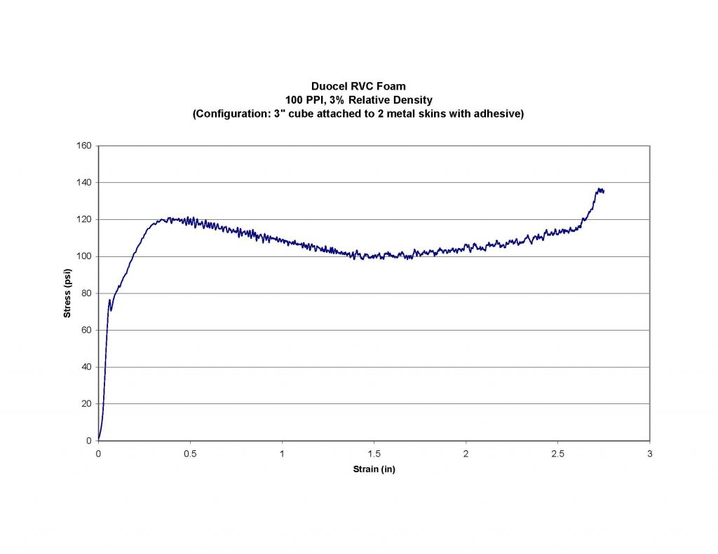
Duocel® metal foam materials are porous structures and they have a unique stress strain curve as reproduced below.
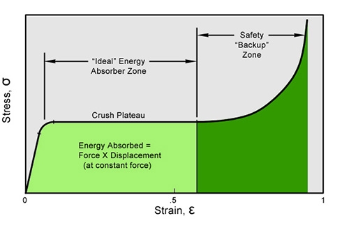
Once an applied stress exceeds the crush plateau, foam will begin to compress at a fairly constant stress out to about 50-70% of strain. This extended section of the stress / strain curve defines the behavior of an ideal energy absorber. In this zone, the area under the curve represents the product of stress × strain, or “work”. In an actual foam block of finite size this would be represented as:
Force × Displacement
Recognizing that
Force (pounds) x Displacement (feet) = Work (foot • pounds)
and
Work (foot • pounds) = kinetic energy (foot • pounds)
It can be seen that the work that is done by compressing a foam block is equivalent to the kinetic energy of a mass that might impact that block. If properly designed with appropriate thickness and compression strength, a foam block could absorb all of the energy of an impacting mass. Most importantly, the structure the foam block was attached to (and protecting) would never see a force higher than the foam crush strength. Thus, by absorbing the energy of the impacting mass over a controlled distance with a constant force, the protected structure would not have to endure a concentrated high-energy / high force impact that would occur if the mass impacted the structure directly, with potentially catastrophic results.
This is the theory behind extended automobile bumpers that stroke with a fixed force under impact load to eliminate or minimized damage to the vehicle and its occupants.
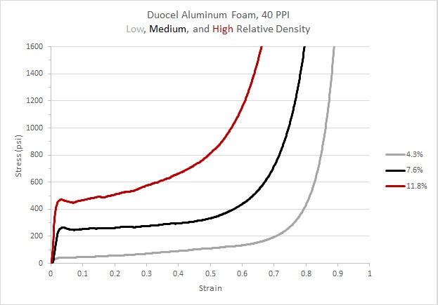
Aluminum Stress/Strain
Coupons are 2.0″ x 2.0″ x 2.5″ and tested per ISO 13314-2011
Processed from 6101 alloy, heat treated to T6 condition
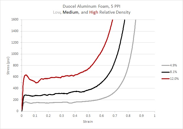
Plateau Stresses
4.9%: 152 psi
8.1%: 311 psi
12.0%: 603 psi
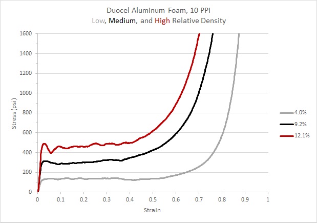
Plateau Stresses
4.0%: 135 psi
9.2%: 318 psi
12.1%: 483 psi
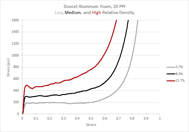
Plateau Stresses
5.7%: 188 psi
8.3%: 336 psi
11.7%: 562 psi
Plateau Stresses
4.3%: 72 psi
7.6%: 278 psi
11.8%: 576 psi
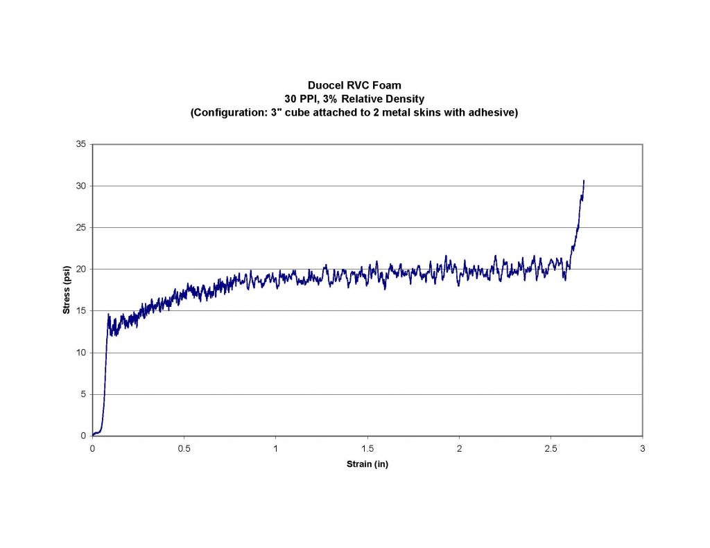
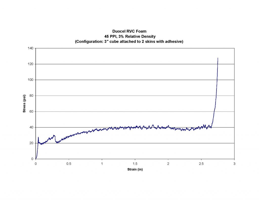
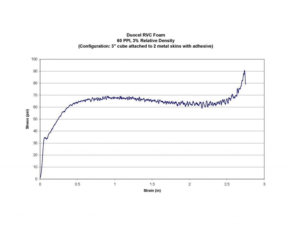
Carbon Stress/Strain
While the first half of the foam stress / strain curve is the section generally used in the design of any foam energy absorber, the second half, or safety “back-up” zone section represents a special energy absorption reserve. When designing energy absorbers, you have to proceed with the best data available. If the situation is critical enough to need an energy absorber in the first place, it is also prudent to provide some form of reserve capacity in the event the impact loads are not fully known, and could be significantly exceeded. By using the increasing stress / strain curve in the densification section, this allows unexpected energy to be absorbed with an increasing resistance. The payload being protected might experience higher than normal loading and minor damage in this case. However, it is less than would be experienced if the energy absorber had a completely flat stress / strain curve and it fully “bottomed out” in a hard, catastrophic impact at the strain limit.
Crush Strength
There are a number of foam mechanical characteristics, but next to modulus, the most frequently used is the crush strength or plastic yield strength. When a load is applied to a foam structure, it will initially yield elastically in accord with the Young’s Modulus equation. However, at approximately 4-6% of strain, depending on the sample size, the foam structure will begin to buckle and collapse continuously at a relatively constant stress. Depending upon the initial relative density of the foam, this constant collapse will proceed to approximately 50-70% of strain. At that point, the stress / strain curve will begin to rise as the compressed foam enters the “densification” phase. The point in the stress / strain curve where it transitions from the elastic to plastic deformation phase defines the “crush strength” of the foam. This is an important mechanical parameter as it is obviously essential to remain below that level for any structure that is being designed to maintain its shape under design load.
On the other hand, the long, relatively flat section of the curve between the 4-6% transition and 50-70% represents a significant amount of “Work” where Work is defined as = Force × Displacement. This unique characteristic of porous materials makes them very useful as energy absorbers where the kinetic energy of an impacting mass can be absorbed with a controlled load, (represented by the “crush strength”) on the parent support structure.
Given that the crush strength is an important design characteristic in both rigid and collapsible foam structures, it is convenient that the equation that defines the crush strength is nearly as simple and as elegant as that which defines the foam modulus.
- Crush Strengthfoam = ~ .58 × tensile yieldsolid × relative density3/2
Where
- Crush strengthfoam = stress at which continuous plastic collapse begins
- ~ .58 = coefficient to correlate to actual compression data
- tensile yieldsolid = tensile yield of the solid material of the foam struts
- relative density = % relative density in decimal form, i.e. 10% = .1
While similar to the equation for modulus, there are a few issues to be aware of.
- It may seem counterintuitive that the equation for the compressive or crush strength of a foam structure contains the tensile yield strength of the solid. This is because the foam structure actually crushes by buckling and plastically bending the “beams” or ligaments of the structure. Plastic beam bending in turn is controlled by the tensile yield strength of the strut material.
- The crush strength or crush plateau is defined as the stress at which continuous collapse is instigated at a relatively constant stress. There is however, a transition zone between the elastic yield and the plastic yield that must be monitored. Any rigid design needs to remain below it, and any energy absorber must remain above it.
- The coefficient ~.58 is somewhat of a catch-all term that addresses both legitimate technical inputs in the equation and unknown variables such as the assumed yield strength for the solid material. (See summary below).
- Tensile yieldsolid is the normal mechanical parameter for the solid material of the struts. While this data is readily available for most foam materials, the data is not always exactly applicable as it is typically derived from ASTM standard tensile test specimens that are relatively large in diameter compared to the .004″ to .010″ diameter ligaments common in foam structures. It is known that tensile test specimen sizes are established to avoid variations due to crystal sizes and other small-scale variables; hence it should not be surprising that the small strut diameters of foams will be subject to these variables. It is therefore essential that caution be used when applying these equations. For example, when designing energy absorbers where the crush strength must be accurately known, initial design can be done using the equations, but final design should be determined by examining actual foam crush test data (see foam material sections) where the foam samples have been manufactured and heat treated in a manner identical to the intended product. As noted in item 3 above, the coefficient is usually adjusted as necessary to compensate for such unknowns.
Foam Modulus
When a load is applied to a foam structure, the foam will initially yield elastically. The slope of this initial stress / strain curve is then defined by the stiffness of the foam. The stiffness or Young‘s Modulus of a foam structure is a function of the solid material modulus and the square of the foam structure relative density in the rather simple and elegant equation:
- Modulusfoam = Modulussolid × relative density2
Where
- Modulusfoam = Young‘s Modulus of the isotropic foam structure
- Modulussolid = standard Young‘s Modulus of the solid strut material
- relative density = % foam relative density in decimal form, i.e. 10% = .1
Unlike foam density, and thermal or electrical conductivity, which are direct functions of the foam relative density, the modulus of the foam structure is a squared function of the relative density. This dominance of relative density in controlling foam modulus over a very wide range provides a particularly powerful design tool. Accordingly, requirements for a “more rigid foam like steel” can actually be easily met by simply increasing the relative density of an aluminum foam by a few percentage points.
Advantages over Other Energy Absorbers
There are a number of porous structures that are used as energy absorbers. Polystyrene shipping “peanuts”, honeycomb, and polyurethane foam seat cushions are just a few typical examples. All of these materials have perfectly justifiable uses but they do have limitations as noted below:
- Polymer–based foams and honeycombs have stress / strain curves that are significantly affected by temperature, age, exposure to ultraviolet light, solvents, and other environmental factors.ERG Duocel® foams, being made of metals, carbon, and ceramics, are comparatively insensitive to these environmental factors, and thus they can reliably provide predictable energy absorption performance after even years of storage or exposure in extreme military standard environmental conditions.
- Honeycombs exhibit their characteristic stress / strain curve only if the compression direction is within a few degrees of their orthogonal cell axis, or if they are constrained in a tube to prevent lateral buckling.Unlike honeycombs, which are considered one-directional, or “orthotropic” foams, Duocel® has the same structure in all three dimensions and is defined as an “isotropic” foam. Accordingly, Duocel® has the same stress / strain curve regardless of impact direction. This makes it particularly useful in situations where there could be unpredictable variations in the direction and magnitude of an impact.
- Honeycombs and closed-cell foams trap gasses within their cells, thus adding a pneumatic “spring” effect that not only disrupts the flat crush plateau, but can add a “rebound” behavior that partially negates the original energy absorption curve.
Duocel foams are also open-celled, so they do not hermetically trap gasses that can create a pneumatic “spring “effect at low impact velocities or create rebound. At very high velocities, there is a fluid flow friction effect as the entrained gas is rapidly squeezed out of the open-celled foam structure. In this case, there is still no effective spring-back, but the increased initial resistance can provide a convenient “crush plateau enhancement” if the impact is at a much higher velocity than anticipated. If this feature is intentionally incorporated into the design, it can be controlled by selection of the foam pore size and airflow resistance.